COPING A CHANNEL Coping a channel in SolidWorks can be easy. Here are some easy to follow steps to help you get the job done. Start with the model of a Structural Channel, like the one shown in Figure 1. |
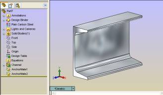
Figure 1
| Add a plane at 45° to the web of the channel. See Figure 2. - Select the face.
- Hold [CTRL] while selecting edge (highlighted in light green).
- In the pull-down menus, select Insert | Reference Geometry | Plane or click on the Reference Plane on the toolbar.
- Set angle to 45°.
- Click OK when done.
|
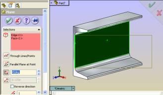
Figure 2
| Create a sketch on the new plane then create an Intersection Curve on plane. See Figure 3. - Right click on web face and select Select Tangency
- Hold [CTRL] while selecting new plane.
- In the pull-down menus, select Tools | Sketch Tools | Intersection Curve.
The resulting sketch should look like the sketch in Figure 4. |
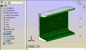
Figure 3
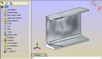
Figure 4
| Extrude cut along edge of channel. See Figure 5. - In the pull-down menus, select Insert | Cut | Extrude or select Extruded Cut on toolbar.
- Select the direction field in the property manager (highlighted in salmon), and select top edge on part (highlighted in light green).
- Click OK when done
|
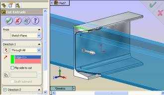
Figure 5
| Add additional feature as necessary to clean up the remaining edge(s) to look like the part at right. See Figure 6. - Start from a face that was created, in the previous step, then cut extrude thru all. NOTE: If you start from the end, then cut to face or vertex, the mirrored features cannot be built because they will not be able to find the face or vertex to extrude up to.
All of the features created in these steps can now be mirrored to the opposite end of the channel. |
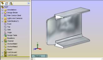
Figure 6
|
These are basic steps for creating a cope on the end of a structural channel. These same steps can be used, with only slight variation, for many other types of structural or extruded shapes. |
 Welcome